Using a 1.44″ Color LCD with Arduino as a display

Recently purchased a cheap color LCD from Ebay (http://www.ebay.com/itm/1-44-Red-Serial-128X128-SPI-Color-TFT-LCD-Module-Display-Replace-Nokia-5110-LCD-/310876068105?hash=item4861a85909:g:9LoAAOSwpzdWqdY~). They are really good for displaying anything (from an Arduino perspective) in color.

Though the are cheap and nice, but finding the proper library for them can be a pain. It would be wise to check the details of the LCD and availability of it’s library first before buying.

What I found so far is there are mainly two types of LCDs that are cheaply available on Ebay. One based on the ILI9163 chipset and another based on the ST7735 chipset.

Arduino IDE from version 1.0.5 onwards comes with a LCD library, which is based on the ST7735 chipset and an advancement of the Adafruit Libraries. Please see this article for more details.

Using the LCD is not much complicated but only thing to remember is there is a huge lot of confusion with which one supports what voltage and I/O levels. So with mine I started with 3.3v and things are working fine.

LED         Connect to +ve supply through a resistor
SCK         13 (fixed as per library)
SDA         11 (fixed as per library)
A0/DC        7 (can be any)
RESET        4   (can be any)
CS           5 (can be any)
GND         GND   
VCC         3.3v

There is one limitation to all libraries (I tested) at the moment, updating the texts on the display. The only way to clear the LCD is by calling the background function and painting the LCD with a color. This gives flicker, as a full screen text takes a bit time to get written fully. Yet to find a solution to this. In the below code only the area that needs to be updated is being cleared.

#include <SFE_BMP180.h> //from sparkfun 
#include <Wire.h>
#include <SoftwareSerial.h>

//#include <Adafruit_GFX.h>
#include <TFT.h> //comes with Arduino IDE 1.0.5 onwards
#include <SPI.h>

// Define pins for ILI9163 SPI myDisplay
#define __CS 5
#define __DC 7 // Labeled as A0 in some modules
#define __RST 6
// Connect SDA to Arduino pin 11 (MOSI), and SCK to 13 (SCK)

char printBuffer[32];

// Color definitions
#define BLACK 0,0,0
#define BLUE 0,0,255
#define RED 255,0,0
#define GREEN 0,255,0
#define CYAN 0,255,255
#define MAGENTA 255,0,255
#define YELLOW 255,255,0 
#define WHITE 255,255,255
#define TRANSPARENT -1
TFT myDisplay = TFT(__CS, __DC, __RST);


//#include <dht11.h>
//dht11 DHT11;


#include "DHT.h"
#define DHTPIN 2
#define DHTTYPE DHT22   // DHT 22  (AM2302), AM2321
DHT dht(DHTPIN, DHTTYPE);


#define _SS_MAX_RX_BUFF 128 // RX buffer size //BEFORE WAS 64


SoftwareSerial esp8266(8,7); //RX,TX

String inputBuffer = "";
String slength;
String sTemp;
boolean stringComplete = false;
int inputBufferIndex;

String data1 = ""; 
String data2 = "";
String data3 = "";
String data5 = "";

SFE_BMP180 pressure;

char status;
double T,P,temp,paH,paM, tempHighest = 0.00, tempLowest = 100.00;

float humHighest = 0.00, humTemp = 0.00, humMin = 100.00;

float lmHighest = 0.00, lmTemp = 0.00, lmMin = 100.00;

unsigned long startTimeDataCapture = 0;
unsigned long lastCapture = 0;

void setup() {
  // put your setup code here, to run once:  
  inputBuffer.reserve(256); //to be optimized
  
  pressure.begin();

  dht.begin();

  pinMode(A0,INPUT);
  analogReference(INTERNAL);

 myDisplay.begin();
 myDisplay.setRotation(4);
 myDisplay.setTextSize(1);
 //myDisplay.setBitrate(24000000);
 //myDisplay.clearScreen();
 myDisplay.background(0,0,0);

 myDisplay.stroke(CYAN);
 myDisplay.setCursor(5,40);
 myDisplay.print("Cur :");
 myDisplay.setCursor(5,50);
 myDisplay.print("Min :");
 myDisplay.setCursor(5,60);
 myDisplay.print("Max :");

 myDisplay.stroke(YELLOW);
 myDisplay.setCursor(5,75);
 myDisplay.print("Hum :");
 myDisplay.setCursor(5,85);
 myDisplay.print("Min :");
 myDisplay.setCursor(5,95);
 myDisplay.print("Max :");

 myDisplay.stroke(WHITE); 
 myDisplay.setCursor(5,110);
 myDisplay.print("PAH :");
 myDisplay.setCursor(5,120);
 myDisplay.print("PAM :");

 myDisplay.stroke(GREEN); 
 myDisplay.setCursor(5,135);
 myDisplay.print("L_C :");
 myDisplay.setCursor(5,145);
 myDisplay.print("L_M :");
  
  Serial.begin(9600);

  esp8266.begin(115200);
  esp8266.println("AT");  delay(100);
  esp8266.println("AT+UART_CUR=4800,8,1,0,0"); esp8266.flush(); delay(100);
  while(esp8266.available())
  {
      //Serial.write(esp8266.read());
      esp8266.read();
      delay(80);
  }
  esp8266.end();

  esp8266.begin(4800);
  esp8266.println("AT"); delay(100);
  
  esp8266.println("AT+CIPMUX=1"); delay(100);
  esp8266.println("AT+CWMODE=1"); delay(100);
  //esp8266.println("AT+CWJAP="xxxxxxxxxxxxx","xxxxxxxxxxxxx""); esp8266.flush(); delay(1000);  
  //esp8266.println("AT+CWJAP="xxxxxxxxxxxxxxxx","xxxxxxxxxxxxxx""); esp8266.flush();  delay(1000);  
  
  while(esp8266.available())
  {
      //Serial.write(esp8266.read());
      esp8266.read();
      delay(80);
  }
    
  delay(1000);
}


void loop() {

  //myDisplay.setCursor(0,40);
  
  while(esp8266.available())
  {
      //Serial.write(esp8266.read());
      esp8266.read();
      delay(10);
  }

  inputBuffer = "";
  stringComplete = false;
  
  status = pressure.startTemperature();
  if (status != 0)
  {
    // Wait for the measurement to complete:
    delay(status);

    // Retrieve the completed temperature measurement:
    // Note that the measurement is stored in the variable T.
    // Function returns 1 if successful, 0 if failure.

    status = pressure.getTemperature(T);
    if (status != 0)
    {
      // Print out the measurement:
      temp = T;
            
      // Start a pressure measurement:
      // The parameter is the oversampling setting, from 0 to 3 (highest res, longest wait).
      // If request is successful, the number of ms to wait is returned.
      // If request is unsuccessful, 0 is returned.

      status = pressure.startPressure(3);
      if (status != 0)
      {
        // Wait for the measurement to complete:
        delay(status);

        // Retrieve the completed pressure measurement:
        // Note that the measurement is stored in the variable P.
        // Note also that the function requires the previous temperature measurement (T).
        // (If temperature is stable, you can do one temperature measurement for a number of pressure measurements.)
        // Function returns 1 if successful, 0 if failure.

        status = pressure.getPressure(P,T);
        if (status != 0)
        {
          // Print out the measurement:
          paM = P;
          paH = P*0.0295333727;
        }
        else
        {
          paM = -1;
          paH = -1;
        }
      }
      else
      {
          paM = -1;
          paH = -1;
      }
    }
    else
    {
      temp = -1;
    }
  }
  else
  {
    temp = -1;
  }

  if(tempLowest > temp)
    tempLowest = temp;

  if(tempHighest < temp)
    tempHighest = temp;

  myDisplay.fill(BLACK);
  myDisplay.stroke(BLACK);
  myDisplay.rect(45,40,75,10);
  myDisplay.setCursor(45,40);
  myDisplay.stroke(CYAN);
  myDisplay.println(String(temp) + (char)248 +"C");
  //delay(100);
  myDisplay.fill(BLACK);
  myDisplay.stroke(BLACK);
  myDisplay.rect(45,50,75,10);
  myDisplay.setCursor(45,50);
  myDisplay.stroke(CYAN);
  myDisplay.println(String(tempLowest) + (char)248 +"C");
  //delay(100);
  myDisplay.fill(BLACK);
  myDisplay.stroke(BLACK);
  myDisplay.rect(45,60,75,10);
  myDisplay.setCursor(45,60);
  myDisplay.stroke(CYAN);
  myDisplay.println(String(tempHighest) + (char)248 +"C");

  delay(500);

  humTemp = dht.readHumidity();
  if(humHighest < humTemp)
    humHighest = humTemp;
  if(humMin > humTemp)
    humMin = humTemp;  
  sTemp = String(humTemp) + "%  " + dht.readTemperature();
  myDisplay.fill(BLACK);
  myDisplay.stroke(BLACK);
  myDisplay.rect(45,75,80,10);
  myDisplay.setCursor(45,75);
  myDisplay.stroke(YELLOW);
  myDisplay.println(sTemp);
  myDisplay.fill(BLACK);
  myDisplay.stroke(BLACK);
  myDisplay.rect(45,85,80,10);
  myDisplay.stroke(YELLOW);
  myDisplay.setCursor(45,85);
  myDisplay.println(humMin);
  myDisplay.fill(BLACK);
  myDisplay.stroke(BLACK);
  myDisplay.rect(45,95,80,10);
  myDisplay.stroke(YELLOW);
  myDisplay.setCursor(45,95);
  myDisplay.println(humHighest);

  delay(500);

  myDisplay.fill(BLACK);
  myDisplay.stroke(BLACK);
  myDisplay.rect(45,110,75,10);
  myDisplay.stroke(WHITE);
  myDisplay.setCursor(45,110);
  myDisplay.println(String(paH));
  //delay(500);
  myDisplay.fill(BLACK);
  myDisplay.stroke(BLACK);
  myDisplay.rect(45,120,75,10);
  myDisplay.stroke(WHITE);
  myDisplay.setCursor(45,120);
  myDisplay.println(String(paM));

  
  lmTemp=analogRead(A0); // reads the sensor output
  lmTemp=lmTemp*0.10546875;
  // converts the sensor reading to temperature
  if(lmHighest < lmTemp)
    lmHighest = lmTemp;
  if(lmMin > lmTemp)
    lmMin = lmTemp;  
  myDisplay.fill(BLACK);
  myDisplay.stroke(BLACK);
  myDisplay.rect(45,135,75,10);
  myDisplay.stroke(GREEN);
  myDisplay.setCursor(45,135);
  myDisplay.println(String(lmTemp));
  //delay(500);
  myDisplay.fill(BLACK);
  myDisplay.stroke(BLACK);
  myDisplay.rect(45,145,75,10);
  myDisplay.stroke(GREEN);
  myDisplay.setCursor(45,145);
  myDisplay.println(String(lmMin));
     
 
  if(millis() - lastCapture >  300000)
  {
    lastCapture = millis();
    
    esp8266.println("AT+CWJAP="xxxxxxxxxxxxxxxx","xxxxxxxxxxxxxxxxxx""); esp8266.flush();  delay(5000);
    
    data1 = "GET /interface_1.php?action=1&temp="+String(temp)+"&paM="+String(paM)+"&paH="+String(paH)+" HTTP/1.1";
    data2 = "Host: 128.199.183.127";
    data3 = "User-Agent: IOT";
    data5 = "Connection: close";
    
    Serial.println(data1);
    //Serial.println(data1.length()+data2.length()+data3.length()+data4.length()+data5.length());
       
    esp8266.println("AT+CIPSTART=4,"TCP","xxx.xxx.xxx.xxx",nn");  delay(1000); 
    while(esp8266.available())
    {
        //Serial.write(esp8266.read());
        esp8266.read();
        delay(10);
    }
  
    slength = String(data1.length()+data2.length()+data3.length()+data5.length()+12);
    esp8266.println("AT+CIPSEND=4,"+slength);
    delay(1000);
    while(esp8266.available())
    {
        //Serial.write(esp8266.read());
        esp8266.read();
        delay(10);
    }
    
    // put your main code here, to run repeatedly:
    esp8266.println(data1); delay(1);
    esp8266.println(data2); delay(1);
    esp8266.println(data3); delay(1);
    esp8266.println(data5); delay(1);
    esp8266.println();  delay(1); esp8266.flush();
  
    while(1)
    {
      if(esp8266.available())
        inputBuffer += (char)esp8266.read();
        
      if(inputBuffer.indexOf("CLOSED")> 0 || millis() - startTimeDataCapture > 10000) //don't wait more than 20 seconds
      {
        stringComplete = true;
        Serial.println(inputBuffer);
        delay(1);
        break;
      }
    }
    esp8266.println("AT+CIPCLOSE=4");
    delay(10);
    esp8266.println("AT+CWQAP");
  }
  
  delay(1000);
  
  
}

An Arduino Pro Mini running at 3.3v will be suitable for this. There will be no need of the logic level converters.
Arduino Voltmeter – 2 (more precise)

On some Arduino boards there is a Pin labelled as AREF or Analog Reference. This pin is very useful in cases where a stable and precise voltage reference is needed for the ADC. Practically the supplied voltage to the board can vary a bit, specially it can fall below the rated voltage depending on the load to the board.

By default Arduino uses the voltage of the board, that is 5v or 3.3v (depending on the board). Using the function analogReference() this can be changed. The function accepts one parameter called type. If the type mentioned is DEFAULT then it will use the voltage of the board. INTERNAL type will use a built-in reference equal to 1.1 volts on the ATmega168 or ATmega328 and 2.56 volts on the ATmega8. And EXTERNAL will use the voltage supplied to the AREF pin. 

(More about analogReference can be read at https://www.arduino.cc/en/Reference/AnalogReference)

Please note the voltage at AREF can 0-5 volts only and the input voltage at the I/O pin (here A0) cannot exceed that of the AREF pin.

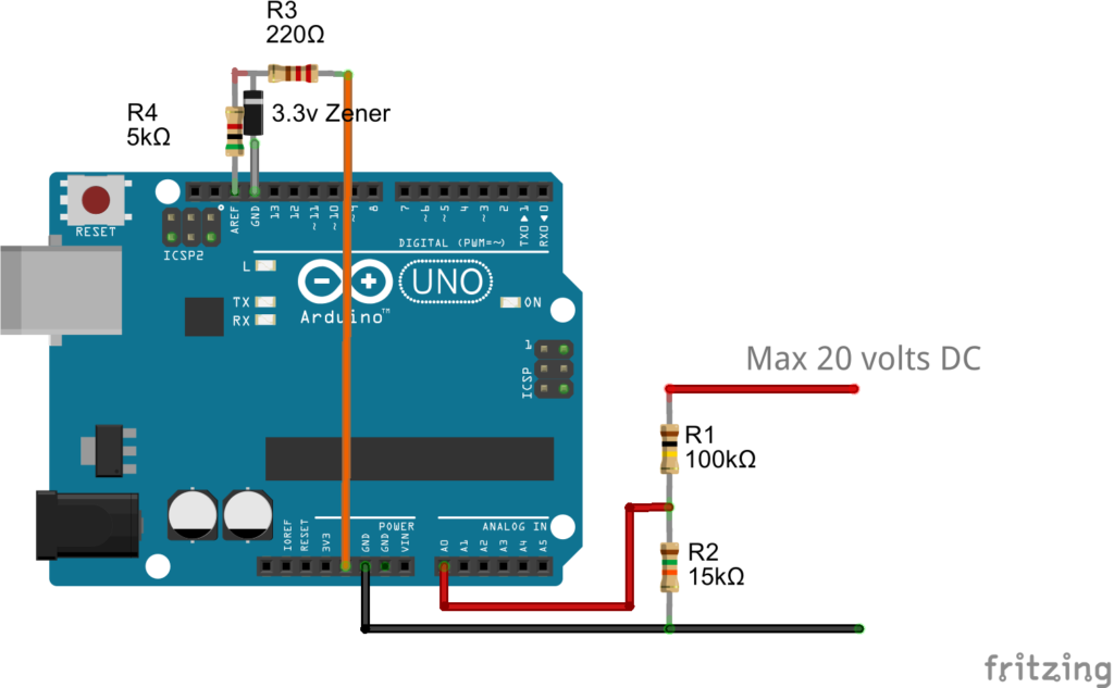
The simple voltmeter described in a previous article has been modified here. It is now supplied with a precise reference voltage at the AREF pin.

Volt Meter Precise

The 5K resistance is not a necessity, it has been added for safety (switching to the INTERNAL while external power is given to AREF can damage the board with that resistance). If the resistance is used then the voltage at AREF will not be exact as supplied. That is because internally there is a 32k resistor connected to the AREF pin.

So in above case the voltage that the AREF actually getting is 3.3*32/(32+5) = 2.8540 (the actual will vary due to tolerance of components, so for cases where high precision is needed, the values of the resistors will have to be measured and also the voltage of the zener, and the voltage in the code nees to be changed accordingly).

#define READINGS 5

int sensorPin = A0;
short int readingsTaken = 0;
float voltage = 0.0, readingTotal = 0.0;

void setup() {
  // put your setup code here, to run once:
  pinMode(sensorPin, INPUT);
  analogReference(EXTERNAL);
  Serial.begin(9600);
}

void loop() {
  // put your main code here, to run repeatedly:
  readingTotal = 0.0;
  readingsTaken = 0;
  
  // we will take 5 readings at 1 sec interval and then do an average of that
  while(readingsTaken < READINGS) 
  {
    readingTotal += analogRead(sensorPin);
    readingsTaken++;
    delay(1000); //at every 1 second interval
  }

  voltage = (readingTotal/READINGS) * (2.8540/1024); // 2.8540 is the ref voltage being used. //the value in voltage at this point is what Arduino read based on input from voltage divider network. Need to calculate the original -- see below

  voltage = (20/2.609) * voltage; //unitary method to calculate the actual voltage that is read. When voltage read is 2.609, the input is 20v. With the above voltage divider used at input (100K ohm and 15k ohm) the input voltage at the I/O (pin A0) will be 2.609 when 20v is applied. 
   
  Serial.println(voltage); 
}

Voltmeter using Arduino

Using precisely calculated resistors and a stable power supply, Arduino can be used to work as a voltmeter.

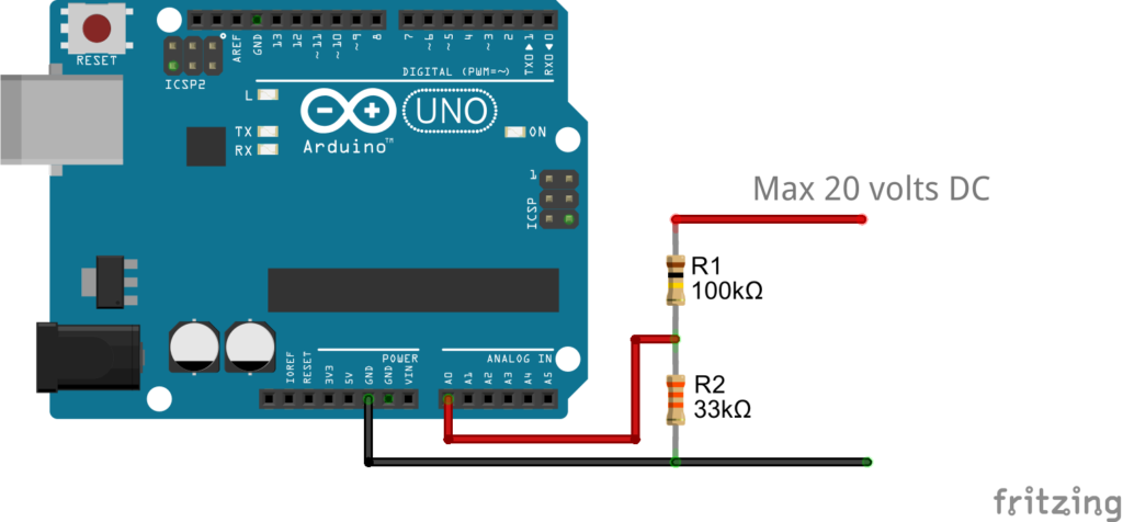
Below is the schematic

Arduino Voltmeter

Though I used an Arduino Uno, but any Arduino can be used. (If the 3.3v versions are used then calculations will have to be done accordingly).

The resister for voltage divider has been chosen such that at 20 volts (measurement) supply the voltage at Arduino input pin is 5.0v. Greater than 5v at the input pin can damage the pin.

Here is the code

#define READINGS 5

int sensorPin = A0;
short int readingsTaken = 0;
float voltage = 0.0, readingTotal = 0.0;

void setup() {
  // put your setup code here, to run once:
  pinMode(sensorPin, INPUT);
  Serial.begin(9600);
}

void loop() {
  // put your main code here, to run repeatedly:
  readingTotal = 0.0;
  readingsTaken = 0;
  
  // we will take 5 readings at 1 sec interval and then do an average of that
  while(readingsTaken < READINGS) 
  {
    readingTotal += analogRead(sensorPin);
    readingsTaken++;
    delay(1000); //at every 1 second interval
  }

  voltage = (readingTotal/READINGS) * (5.0/1024); // the value in voltage at this point is what Arduino read based on input from voltage divider network. Need to calculate the original // 5.0 - is the ref voltage used by ADC. It is the default configuration and uses the voltage supplied to the board. To change the ref voltage/source please see this article

  voltage = (20/4.992) * voltage; //unitary method to calculate the actual voltage that is read. When voltage read is 4.922 (or 5.0v), the input is 20v. With the resistor divider at the input, the voltage at I/O will be 4.992

  Serial.println(voltage);
}

This is a simple and basic way. Where the precision will not be very good. Because the reference voltage being used by the ADC, which is actually the supply voltage can vary depending on the load to the circuit. To make it more precise an external reference voltage can be supplied to the Arduino. How to use an external reference voltage and the use of the AREF pin has been described in this article

GPS Tracker Using NEO 6M and ESP-12

The below code outputs current co-ordinate and speed in km/hr . The code is a first draft and there are optimizations to be done. It uses a Ublox NEO 6M for the GPS module and an ESP-12 (of the ESP 8266 family) for the collecting the GPS data from the NEO 6M module, processing the data and outputting in JSON format.

The ESP-12 is working as a webserver. When connected it first asks for the WiFi password set in the code as “WiFiAPPSK”. And for an added layer of security a password is also needed with the HTTP request. (This will made proper in future).  Without the password the server will reject the request.

Arduino IDE is used for programming the ESP-12.


//#include <SoftwareSerial.h> //causing the module to reset automatically intermittently
#include <ESP8266WiFi.h>
#include <EEPROM.h>

//SoftwareSerial gps(14,12);

char WiFiAPPSK[] = "123456#";
char savedPass[9] = "12345678", suppliedPass[9], hashedPass[9];
int addr = 0;

short int resetWifiFlag = 0;

WiFiServer server(80);

void encodePass(char *pass, char *hash) //encoding using XOR, need to change as this generates characters that causes problems while passed through GET method
{
  short int i;
  char key[9] = "ikirmiki"; //8 chars
  
  i = strlen(pass);
  
  //i is pointing at the end of the string. Now fillup the rest string with NULL
  for(; i<=9; i++)
  {
    pass[i] = '\0';
  }
  //at this point the pass is filled with pass and all empty cells are filled with NULL
  //now let's do the XOR
  for(i=0; i<=9;i++)
  {
    //hash[i] = pass[i] ^ key[i];
    *(hash+i) = *(pass+i) /*^ key[i]*/;
  }
}

void decodePass(char *pass, char *hash)
{
  short int i;
  char key[9] = "ikirmiki"; //8 chars
  
  //check the hash by decoding
  //now let's do the XOR
  for(i=0; i<=9;i++)
  {
    *(pass+i) = *(hash+i) /*^ key[i]*/; //Overridden for now as XOR creates some special characters sometimes which is not being interpreted by browser address bar properly.
  }
}

void explodeString(char *delimiter, char *str, char explodedArray[][32]) 
{
  int i = 0;
  char* token;
  
  token = strtok(str, delimiter);
  while(token != NULL)
  {
     //explodedArray[i] = (char *)malloc(strlen(token)+1);
     strcpy(explodedArray[i++],token);delay(1);
     token = strtok(NULL, delimiter);
  }
}


short int ensure8CharPass(char *pass, char *tempPass) //for the XOR ing with 8 chars key we need to ensure the pass is also 8 chars
{
  short int i;

  for(i=0;i<9;i++)
  {
    pass[i]=tempPass[i];
  }
  pass[i] = '\0';
  
  if(strlen(pass) != 8)
  {
    return 0;
  }
  else
  {
    return 1;
  }
}

String getSpeed(String rawLatLong)
{
  int firstPos, lastPos = 0;
  int i;

  firstPos = rawLatLong.indexOf("$GPVTG,");
  for(i=0; i < 7; i++)
  {
    firstPos = rawLatLong.indexOf(",", firstPos+1); //$GPVTG,279.67,T,,M,4.903,N,9.080,K,A*3F -- go to 9.080
    delay(1); 
  }
  firstPos = firstPos + 1; //skip the comma that is infront of 9.080
  lastPos = firstPos;
  for(i=0; i < 2; i++) //go to the comma after K
  {
    lastPos = rawLatLong.indexOf(",", lastPos+1);
    delay(1);
  }
  return rawLatLong.substring(firstPos,lastPos);
}


String getLatLong(String rawLatLong)
{
  int firstPos = 0, lastPos = 0, i, degree;
  char latLong[5][32], buff[64];
  float latitude, longitude, minute;
  String temp;

  firstPos = rawLatLong.indexOf("$GPRMC,"); //same concept as in above ($GPVTG)
  for(i=0; i < 3; i++)
  {
    firstPos = rawLatLong.indexOf(",", firstPos+1);
    delay(1);
  }
  firstPos = firstPos + 1; //skip the comma -- same concept as in above ($GPVTG)
  lastPos = firstPos;
  for(i=0; i < 4; i++)
  {
    lastPos = rawLatLong.indexOf(",", lastPos+1);
    delay(1);
  }
  
  temp = rawLatLong.substring(firstPos,lastPos); delay(1); // delay(1) need to checked if necessary or not. 
  temp.toCharArray(buff,64); delay(1); // delay(1) need to checked if necessary or not.
  explodeString(",",buff,latLong); delay(1);  // delay(1) need to checked if necessary or not.
  //at this point latLong must have all the elemnts in consequetive array
  //convert the values in position 0 and 2
  //fist check if the values at those positions are valid or not
  if(strlen(latLong[0]) && strlen(latLong[2])) //convert to decimal format from degree, minute
  {
    latitude = atof(latLong[0]);
    longitude = atof(latLong[2]);
    latitude = latitude / 100;
    longitude = longitude / 100;

    degree = (int)latitude;
    minute = latitude - degree;
    minute = minute * 100;
    latitude = degree + (minute/60);

    degree = (int)longitude;
    minute = longitude - degree;
    minute = minute * 100;
    longitude = degree + (minute/60);

    delay(1); //need to check if needed
    //Serial.println(String(latitude,6)+","+latLong[1]+","+String(longitude)+","+latLong[3]);
    return (String(latitude,6)+","+latLong[1]+","+String(longitude,6)+","+latLong[3]); //String(latitude,6) the second parameter to string sets the precision after decimal. 

    
  }
  else
  {
    return String("Yet to get a fix");
  }
  
}

void writeSettings(int addr, char *toWrite)
{
  int i;
  for(i=0; i<9; i++)
  {
    EEPROM.write((addr+i), toWrite[i]);
  }
  EEPROM.commit();
}

void readSettings(int addr, char *toRead) // will have to change this function - need to make it such t
{
  int i;
  for(i=0; i<9; i++)
  {
    toRead[i] = EEPROM.read((addr+i));
  }
  toRead[i] = '\0';
}

void setupWiFi()
{
  WiFi.mode(WIFI_AP);

  // Do a little work to get a unique-ish name. Append the
  // last two bytes of the MAC (HEX'd) to "Thing-":
  uint8_t mac[WL_MAC_ADDR_LENGTH];
  WiFi.softAPmacAddress(mac);
  String macID = String(mac[WL_MAC_ADDR_LENGTH - 2], HEX) +
                 String(mac[WL_MAC_ADDR_LENGTH - 1], HEX);
  macID.toUpperCase();
  String AP_NameString = "GPS Tracker " + macID;

  char AP_NameChar[AP_NameString.length() + 1];
  memset(AP_NameChar, 0, AP_NameString.length() + 1);

  for (int i=0; i<AP_NameString.length(); i++)
    AP_NameChar[i] = AP_NameString.charAt(i);

  WiFi.softAP(AP_NameChar, WiFiAPPSK);

  resetWifiFlag = 0; //look in loop for explanation
}


void setup() 
{
  // put your setup code here, to run once:
  Serial.begin(9600);
  EEPROM.begin(64); //initiate 64 bytes to write/read
  //gps.begin(9600);
 
  readSettings(addr+0, hashedPass); //read the saved pass at addr+0 location
  if(strlen(hashedPass) == 8) //id the saved password is of proper length then decode it and use it.
    decodePass(savedPass, hashedPass);
    
  strcpy(WiFiAPPSK,savedPass); //set the Wifi Password also
  setupWiFi(); //start the wifi
  
  server.begin();
}

void loop() 
{
  //check if any variable is redundant
  volatile unsigned long startTime, currentTime;
  String serialBuffer, latLong;
  int pos,flag,i,j,temp;
  short int passError = 1, len, latLongFlag = 0, speedFlag = 0;
  char serialDataByte;

  if(resetWifiFlag == 1) // if the password is changed then this will be called to re-initialize the WIFI-AP with the new password
   {
      setupWiFi();
   }
  
  //start the webserver and send the data
  // Check if a client has connected
  WiFiClient client = server.available();
  if (!client) 
  {
    delay(1);
    return;
  }
  else
  {
    delay(1);

    //Read the first line of the request
    String req = client.readStringUntil('\r');

    //now check if password change requested or not
    pos = req.indexOf("/changepass/");
    if(pos != -1)
    {
      //get the new pass
      len = pos+12+8; //12 chars of /changepass/ AND 8 of password
      for(i=pos+12,j=0; i<len; i++,j++)
      {
        if(req.charAt(i) == '/')
          break;
        else
          hashedPass[j] = req.charAt(i);
      }
      hashedPass[j] = '\0';
      decodePass(suppliedPass, hashedPass);
      strcpy(savedPass,suppliedPass);
      //save the password
      //Serial.println("New Pass: "+ String(hashedPass));
      writeSettings(addr+0, hashedPass); //save the password

      //not calling a function for sending the data to save the function call overhead.
      // Prepare the response. Start with the common header:
      String s = "HTTP/1.1 200 OK\r\n";
      s += "Content-Type: application/json\r\n\r\n";
      s += "{"succcess":"Password Changed To: "+ String(suppliedPass)+""}";
      // Send the response to the client
      client.print(s);
      client.flush();
      delay(1);
      client.stop();
      //ESP.restart(); //to make the new password in effect immediately - USING THIS WILL NOT DISPLAY THE RESULT. It seems the loop needs to be exited to send the result to client Using a delay of 10 seconds also didn't work
      //AS THE restart method is not available so setting up the wifi again with the new password
      strcpy(WiFiAPPSK,suppliedPass); //set the Wifi Password also
      resetWifiFlag =1; // if the wifi pass is changed here now then client will loose connection before printing the result. the loop() will have to be exited to print the result. so we are setting the flag here and changing the password in the next iteration of the loop()
      delay(1); //safe side
      return;
    }

    pos = req.indexOf("/pass/");
    if(pos == -1) // that means no password supplied
    {
      //not calling a function for sending the data to save the function call overhead.
      client.flush();
      // Prepare the response. Start with the common header:
      String s = "HTTP/1.1 200 OK\r\n";
      s += "Content-Type: application/json\r\n\r\n";
      s += "{"error":"Auhentication Error 1"}";
      // Send the response to the client
      client.print(s);
      client.flush();
      delay(1);
      client.stop();
      return;
    }
    else
    {
      //Serial.println("Client Connected");
      //read upto the next slash
      len = pos+6+8; //6 chars of /changepass/ AND 8 of password
      for(i=pos+6,j=0; i<len; i++,j++)
      {
        if(req.charAt(i) == '/')
          break;
        else
          hashedPass[j] = req.charAt(i);
      }
      hashedPass[j] = '\0';
      
      //now decode the pass 
      decodePass(suppliedPass, hashedPass);
      if(strcmp(suppliedPass,savedPass))
      {
        //not calling a function for sending the data to save the function call overhead.
        client.flush();
        // Prepare the response. Start with the common header:
        String s = "HTTP/1.1 200 OK\r\n";
        s += "Content-Type: application/json\r\n\r\n";
        s += "{"error":"Auhentication Error 2"}";
        // Send the response to the client
        client.print(s);
        client.flush();
        delay(1);
        client.stop();
        return;
      }
    }
   
    startTime = currentTime = 0;
    serialBuffer = latLong = "";
  
    flag = -1;
    
    startTime = millis();
    
    // put your main code here, to run repeatedly:
    while(flag == -1)  //read 5 seconds of data
    {
      if(Serial.available() > 0)
      {
        serialBuffer += (char)Serial.read();
        if(serialBuffer.indexOf("$GPRMC,") >=0)
        {

          while(1)
          {
            serialDataByte = (char)Serial.read();
            if(serialDataByte == '\r' || serialDataByte == '$') //need to optimize - check if \r is sufficient
            {
              latLong = getLatLong(serialBuffer);
              serialBuffer = serialDataByte; //reset the serial buffer for the next line
              break;
            }
            else
            {
              serialBuffer += serialDataByte;
            }
            delay(1);
          }
        }

        if(serialBuffer.indexOf("$GPVTG,") >=0)
        {
          while(1)
          {
            serialDataByte = (char)Serial.read();
            if(serialDataByte == '\r' || serialDataByte == '$') //need to optimize - check if \r is sufficient
            {
              flag = 1;
              latLong = latLong + "," + getSpeed(serialBuffer);
              latLong = "{"success":""+latLong+""}";
              break;
            }
            else
            {
              serialBuffer += serialDataByte;
            }
            delay(1);
          }
        }
      }

      if(millis()- startTime > 5000)
      {
        //Serial.println("TimeOut");
        latLong = "Timeout"; 
        latLong = "{"error":""+latLong+""}";
        latLongFlag = speedFlag = 0;
        break;
      }
      delay(1);
    } 
    //Serial.println("LN: "+latLong);
  }

  client.flush();
  // Prepare the response. Start with the common header:
  String s = "HTTP/1.1 200 OK\r\n";
  s += "Content-Type: application/json\r\n\r\n";
  //s += "<!DOCTYPE HTML>\r\n<html>\r\n<body>\r\n";
  s += latLong;
  //s += "</body>\r\n</html>\n";
  // Send the response to the client
  client.print(s);
  client.flush();
  //delay(100); Serial.println("Client disonnected");
  latLongFlag = speedFlag = 0;  
  delay(1);
  client.stop();
}


Notes:

  • The setupWifi code is from Sparkfun’s code
  • The Software Serial is causing trouble. The WiFi Access Point (AP) is dying after sometime if the Software Serial Library is used.
  • The delays are needed to allow the ESP8266 to do it’s own internal tasks (like maintaining the wifi connection). The delays are needed where there can be long loops.

ESP8266 Description and Details

ESP 8266 from Espressif is a wifi module with a microcontroller inbuilt. It is cheap and widely available on online stores. Previously the chip could be programmed using LUA only. Now the chip can be programmed using C and also using Arduino IDE. The best part about the Arduino approach is, the codes are similar to Arduino.

There are many versions available.

Here is the documentation of the ESP 8266. For details about programming the ESP8266 using Arduino IDE, please see this article.

ESP8266 Programming Using Arduino IDE

The ESP8266 can be programmed using the Arduino IDE. The best part is the codes are similar to Arduino. To start programming a ESP8266 using Arduino IDE follow the below steps

Prerequisites

Steps

  • Start Arduino and goto File-> Preferences.
  • In the “Additional Boards Manager URLs” Enter http://arduino.esp8266.com/stable/package_esp8266com_index.json  (You can add multiple URLs, separating them with commas)
  • Click “OK”
  • Open Boards Manager from Tools -> Board menu and find esp8266 platform.
  • Select the version you need from drop-down box.
  • Click install button.
  • ——————————————–
  • Upload a blank sketch to the Arduino.
  • Connect RX to RX and TX to TX
  • GPIO_0 will go to GND
  • VCC and CH_PD will go to the 3.3v supply line
  • Select the appropriate ESP8266 board from Tools > Board menu.
  • Select the appropriate Flash mode (DOUT or QIO. See notes below)
  • Other parameters works mostly as it is – but still check once.
  • Start upload
  • RESET the module. This is a critical step and the timing matters. It may need a few tries to get it perfect.

After the code uploaded

  • Disconnect GPIO_0
  • Reset


For further details please check http://esp8266.github.io/Arduino/versions/2.3.0/

Please see this article for a basic code (Blinking LED that is the Hello World of micro-controllers)

Notes

  • While uploading codes through Arduino IDE select DOUT for new chip and either DOUT or QIO for old chips.
  • Keeping it to DOUT will work for both New and Old chips.
  • Burning new chips with QIO (or inappropriate modes) will result in a successful burning but the code will not run.


Here is a Troubleshooting Guide and parameters that worked for me.

Flashing guide for new chips.

ESP 8266 – ESP-12E Hello World – Blinking LED

We are using Arduino IDE to program our ESP8266. Please see this article regarding how to setup the Arduino IDE for programming ESP8266.

Here is a blinking LED code for ESP8266 written in Arduino IDE.

#define ESP8266_LED 5 
void setup() 
{   
   pinMode(ESP8266_LED, OUTPUT); 
} 
void loop() 
{   
   digitalWrite(ESP8266_LED, HIGH);   
   delay(500);   
   digitalWrite(ESP8266_LED, LOW);   
   delay(500); 
}

Instructions:

  • Connect a LED (with a resistor in series) to an I/O pin of your ESP8266. Change the pin number to an appropriate one in the first line of the code.
  • Select the appropriate ESP Board/Version fromthe Boards Menu of the Arduino IDE. If your board is not listed then you can select Generic and then set the parameters according to the chip or module version (ESP-01, ESP-06, ESP-12E etc) you are using.
  • Upload the code to the module.
  • The LED should be blinking now.


UBLOX NEO 6M GPS Module

The NEO 6M from Ublox is a good and affordable GPS module. The characteristics are as follows.

It can be purchased with a ceramic antenna from online stores like Ebay or Aliexpress. Unfortunately the one I purchased had a problem with the Antenna connection due to which some time got wasted in trying to get a fix. After a little bit of tweaking with the antenna connector the module is getting a GPS fix even inside rooms.

I have supplied it with 5v and the RX and TX also has been connected to 5v I/O. There is an indicator (light) on the module that flashes when the module gets a GPS fix. (Please check with your module manufacturer for the correct voltage of the module)

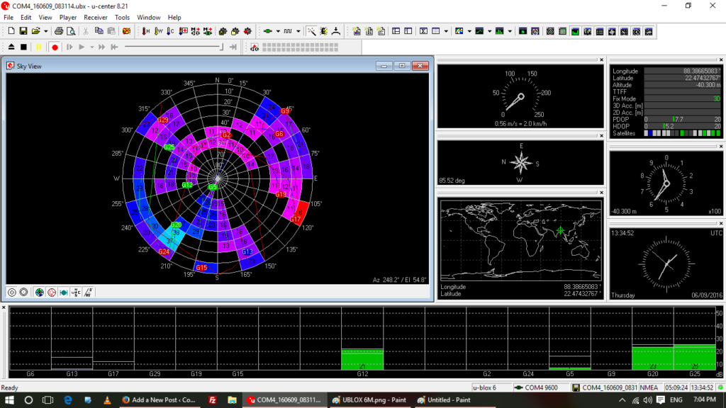
Ublox provides a software called “u-center” for testing the module. But the software is good enough for monitoring also.  The u-center software can also be used to change/update configurations of the module. The software can be downloaded from this Ublox website’s link https://www.u-blox.com/en/product/u-center-windows . And as a backup it has been put up here also (at the time of writing this article the latest version was 8.21).

Ublox u-center software

The module can be connected using a USB to Serial module (PL2303 or CH340G) or using an Arduino. Below is the connection details for connecting through Arduino or USB to RS232 modules.

Connect to PC using Arduino 
Arduino                NEO 6M 
   RX         ----       RX
   TX         ----       TX
   5v         ----       5v
   GND        ----       GND

Connect to PC using USB to Serial Module
USB to RS232             NEO 6M 
 RX              ----       TX
 TX              ----       RX
 5v              ----       5v
 GND             ----       GND


The module works out of the box and no further configuration is required. It might take a while to get a fix.

Here is the datasheet.

The module outputs data in NMEA format. The details of the format can be found here. Here is a copy of the website material in case the site ever goes down (the data is of http://gpsinformation.org)

Please check with your module manufacturer for the correct voltage of the module

Notes:

  • Once the module somehow stopped working and responding. Removing the onboard battery helped. Re-attaching the battery later on didn’t have any problem and the module is working fine. The battery is for data backup, so removing it altogether doesn’t have any problem, just that it takes a lot of time to get a fix when the module is powered up again.

WS2811, WS2812, NeoPixel RGB Pixels/LEDs and Arduino

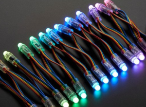
WS28WS281111 or WS2812 based LEDs / RGB pixels are cheap and easily available on the online stores. They run off 5 volts and can be addressed individually. Waterproof versions are also available.

On Ebay/Aliexpress/Alibaba they are sold as a set of 25 leds / RGB pixels connected together. Multiple such strips/chains can be connected together to form longer chains of light.

Unfortunately they mostly come without any power source or controller. Normally for a 25 RGB LED chain based on WS2811 consumes about .3W (please refer to manufacturer datasheet for exact requirements). So it can be powered from almost any ordinary 5v adapter, even mobile phone  chargers (with sufficient current supply capability) can be used.

For controlling the rgb lights and changing colors and effects an Arduino can be used. The “FastLED” project on GitHub is a nice library. It has many examples also. The library supports Arduino and various type of RGB LED / RGB Pixels. Here is the link to the GitHub repository:  https://github.com/FastLED/FastLED.
I am attaching the Master here as on 23-05-2016 in case the library goes off GitHub for some reason. The code belongs to the developers and contributors (https://github.com/FastLED/FastLED/graphs/contributors)
And here is the Arduino Library only as on 23-05-2016. The version is 3.1.0

LM35 Precision Cheap Temperature Sensor

The LM35 from Texas Instruments is a cheap but very good temperature sensor. It is available in various packages. Please refer to the LM35 Temperature Sensor for package and other details.

It can be powered directly from the 5v supply of Arduino.

The chip outputs  10.0 mV per °C. Below is a small snippet of code that can be used to convert the output voltage into temperature.

val = analogRead(tempPin);
mv = ( val/1024.0)*5000;  // mv = (val/1024) * (voltage * 1000) The 1024 is derived from  the fact that the Atmega ADC has 10 bit resolution, returning integers from 0 to 1023.
cel = mv/10; // cel = mv / 10.0 milli volt per °C
farh = (cel*9)/5 + 32;

Please refer the Datasheet for Pin Configuration.